Menü
Kosár

CPU M13C - 16DI / 12 DO / 1AI, 2x RJ45 Modbus TCP/ Ethernet/ Profinet

CPU M13C - 16DI / 12 DO / 1AI, 2x RJ45 Modbus TCP/ Ethernet/ Profinet
186 305 Ft
Nettó ár: 146 697 Ft
  • Készlet: Nincs raktáron
  • Cikkszám: M13-CCF0000
  • Tömeg: 0.3 kg

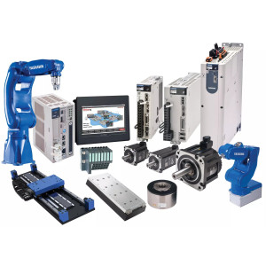
CPU M13C - 16DI / 12 DO / 1AI, 2x RJ45 Modbus TCP/ Ethernet/ Profinet
M13-CCF0000 - Yaskawa Micro PLC CPU S7
Programozható Simatic manager és TIA Portal-on keresztül.  

Kommunikáció

- Profinet
- Modbus RTU / TCP
- OPC UA  /  WebServer 


Termék tudás szintje megfelel: Siemens 1215  - 6ES7215-1HG40-0XB0  (csak 1 Analaóg bemenettel)


M13-CCF0000 - CPUs | CPUs STEP7 programmable, C class

Order no.

M13-CCF0000

Type

CPU M13C

Module ID

-

General information

Note

-

Features

Powered by SPEED7
Work memory [KB]: 64...128
Onboard: 16x DI / 12x DO / 2x AI [voltage 0...10 V] / 4x Counter / 2x [PWM/Pulse Train]
Interface [2x RJ45]: active Ethernet PG/OP communication with DHCP support, switch, ModbusTCP master/slave, openCommunication, I-Device, PROFINET IO controller (8 devices)
Optional: [2x RS485]: MPI, PROFIBUS slave, PtP: ASCII, STX/ETX, 3964 (R), USS master, Modbus master/slave
Web server
SD card slot with locking, up to 8 expansion modules, configurable via SPEED7 Studio, SIMATIC Manager and TIA Portal

Technical data power supply

Power supply (rated value)

DC 24 V

Power supply (permitted range)

DC 20.4...28.8 V

Reverse polarity protection

Current consumption (no-load operation)

120 mA

Current consumption (rated value)

360 mA

Inrush current

3 A

I2t

0.1 A2s

Max. current drain at backplane bus

1 A

Max. current drain load supply

-

Power loss

7 W

Technical data digital inputs

Number of inputs

16

Cable length, shielded

1000 m

Cable length, unshielded

600 m

Rated load voltage

DC 24 V

Reverse polarity protection of rated load voltage

Current consumption from load voltage L+ (without load)

25 mA

Rated value

DC 24 V

Input voltage for signal "0"

DC 0...5 V

Input voltage for signal "1"

DC 15...28.8 V

Input voltage hysteresis

-

Signal logic input

Sinking input

Frequency range

-

Input resistance

-

Input current for signal "1"

3 mA

Connection of Two-Wire-BEROs possible

Max. permissible BERO quiescent current

0.5 mA

Input delay of "0" to "1"

3 µs – 15 ms / 0.5 ms – 15 ms

Input delay of "1" to "0"

3 µs – 15 ms / 0.5 ms – 15 ms

Number of simultaneously utilizable inputs horizontal configuration

16

Number of simultaneously utilizable inputs vertical configuration

16

Input characteristic curve

IEC 61131-2, type 1

Initial data size

16 Bit

Technical data digital outputs

Number of outputs

12

Cable length, shielded

1000 m

Cable length, unshielded

600 m

Rated load voltage

DC 24 V

Reverse polarity protection of rated load voltage

Current consumption from load voltage L+ (without load)

20 mA

Total current per group, horizontal configuration, 40°C

6 A

Total current per group, horizontal configuration, 60°C

6 A

Total current per group, vertical configuration

6 A

Output voltage signal "1" at min. current

L+ (-0.8 V)

Output voltage signal "1" at max. current

L+ (-0.8 V)

Output current at signal "1", rated value

0.5 A

Signal logic output

Sourcing output

Output current, permitted range to 40°C

5 mA to 0.6 A

Output current, permitted range to 60°C

5 mA to 0.6 A

Output current at signal "0" max. (residual current)

0.5 mA

Output delay of "0" to "1"

2 µs / 30 µs

Output delay of "1" to "0"

3 µs / 175 µs

Minimum load current

-

Lamp load

10 W

Parallel switching of outputs for redundant control of a load

not possible

Parallel switching of outputs for increased power

not possible

Actuation of digital input

Switching frequency with resistive load

max. 1000 Hz

Switching frequency with inductive load

max. 0.5 Hz

Switching frequency on lamp load

max. 10 Hz

Internal limitation of inductive shut-off voltage

L+ (-45 V)

Short-circuit protection of output

yes, electronic

Trigger level

1 A

Number of operating cycle of relay outputs

-

Switching capacity of contacts

-

Output data size

12 Bit

Technical data analog inputs

Number of inputs

2

Cable length, shielded

200 m

Rated load voltage

-

Reverse polarity protection of rated load voltage

-

Current consumption from load voltage L+ (without load)

-

Voltage inputs

Min. input resistance (voltage range)

100 k?

Input voltage ranges

0 V ... +10 V

Operational limit of voltage ranges

+/-3.5%

Operational limit of voltage ranges with SFU

-

Basic error limit voltage ranges

+/-3.0%

Basic error limit voltage ranges with SFU

-

Destruction limit voltage

max. 30V

Current inputs

-

Max. input resistance (current range)

-

Input current ranges

-

Operational limit of current ranges

-

Operational limit of current ranges with SFU

-

Basic error limit current ranges

-

Radical error limit current ranges with SFU

-

Destruction limit current inputs (electrical current)

-

Destruction limit current inputs (voltage)

-

Resistance inputs

-

Resistance ranges

-

Operational limit of resistor ranges

-

Operational limit of resistor ranges with SFU

-

Basic error limit

-

Basic error limit with SFU

-

Destruction limit resistance inputs

-

Resistance thermometer inputs

-

Resistance thermometer ranges

-

Operational limit of resistance thermometer ranges

-

Operational limit of resistance thermometer ranges with SFU

-

Basic error limit thermoresistor ranges

-

Basic error limit thermoresistor ranges with SFU

-

Destruction limit resistance thermometer inputs

-

Thermocouple inputs

-

Thermocouple ranges

-

Operational limit of thermocouple ranges

-

Operational limit of thermocouple ranges with SFU

-

Basic error limit thermoelement ranges

-

Basic error limit thermoelement ranges with SFU

-

Destruction limit thermocouple inputs

-

Programmable temperature compensation

-

External temperature compensation

-

Internal temperature compensation

-

Technical unit of temperature measurement

-

Resolution in bit

12

Measurement principle

successive approximation

Basic conversion time

2 ms

Noise suppression for frequency

40 dB

Initial data size

4 Byte

Technical data analog outputs

Number of outputs

-

Cable length, shielded

-

Rated load voltage

-

Reverse polarity protection of rated load voltage

-

Current consumption from load voltage L+ (without load)

-

Voltage output short-circuit protection

-

Voltage outputs

-

Min. load resistance (voltage range)

-

Max. capacitive load (current range)

-

Max. inductive load (current range)

-

Output voltage ranges

-

Operational limit of voltage ranges

-

Basic error limit voltage ranges with SFU

-

Destruction limit against external applied voltage

-

Current outputs

-

Max. in load resistance (current range)

-

Max. inductive load (current range)

-

Typ. open circuit voltage current output

-

Output current ranges

-

Operational limit of current ranges

-

Radical error limit current ranges with SFU

-

Destruction limit against external applied voltage

-

Settling time for ohmic load

-

Settling time for capacitive load

-

Settling time for inductive load

-

Resolution in bit

-

Conversion time

-

Substitute value can be applied

-

Output data size

-

Technical data counters

Number of counters

4

Counter width

32 Bit

Maximum input frequency

100 kHz

Maximum count frequency

400 kHz

Mode incremental encoder

Mode pulse / direction

Mode pulse

Mode frequency counter

Mode period measurement

Gate input available

Latch input available

Reset input available

-

Counter output available

Load and working memory

Load memory, integrated

128 KB

Load memory, maximum

128 KB

Work memory, integrated

64 KB

Work memory, maximal

128 KB

Memory divided in 50% program / 50% data

Memory card slot

SD/MMC-Card with max. 2 GB

Hardware configuration

Racks, max.

1

Modules per rack, max.

8

Number of integrated DP master

-

Number of DP master via CP

-

Operable function modules

-

Operable communication modules PtP

-

Operable communication modules LAN

-

Status information, alarms, diagnostics

Status display

yes

Interrupts

yes, parameterizable

Process alarm

yes, parameterizable

Diagnostic interrupt

yes, parameterizable

Diagnostic functions

yes, parameterizable

Diagnostics information read-out

possible

Supply voltage display

green LED

Group error display

red LED

Channel error display

red LED per group

Isolation

Between channels

Between channels of groups to

16

Between channels and backplane bus

Between channels and power supply

-

Max. potential difference between circuits

DC 75 V/ AC 50 V

Max. potential difference between inputs (Ucm)

-

Max. potential difference between Mana and Mintern (Uiso)

-

Max. potential difference between inputs and Mana (Ucm)

-

Max. potential difference between inputs and Mintern (Uiso)

-

Max. potential difference between Mintern and outputs

-

Insulation tested with

DC 500 V

Command processing times

Bit instructions, min.

0.02 µs

Word instruction, min.

0.02 µs

Double integer arithmetic, min.

0.02 µs

Floating-point arithmetic, min.

0.12 µs

Timers/Counters and their retentive characteristics

Number of S7 counters

512

S7 counter remanence

adjustable 0 up to 256

S7 counter remanence adjustable

C0 .. C7

Number of S7 times

512

S7 times remanence

adjustable 0 up to 256

S7 times remanence adjustable

not retentive

Data range and retentive characteristic

Number of flags

8192 Byte

Bit memories retentive characteristic adjustable

adjustable 0 up to 256

Bit memories retentive characteristic preset

MB0 .. MB15

Number of data blocks

1024

Max. data blocks size

64 KB

Max. local data size per execution level

4096 Byte

Blocks

Number of OBs

22

Number of FBs

1024

Number of FCs

1024

Maximum nesting depth per priority class

16

Maximum nesting depth additional within an error OB

4

Time

Real-time clock buffered

Clock buffered period (min.)

30 d

Accuracy (max. deviation per day)

10 s

Number of operating hours counter

8

Clock synchronization

Synchronization via MPI

Master/Slave

Synchronization via Ethernet (NTP)

no

Address areas (I/O)

Input I/O address area

2048 Byte

Output I/O address area

2048 Byte

Input process image maximal

2048 Byte

Output process image maximal

2048 Byte

Digital inputs

144

Digital outputs

140

Digital inputs central

144

Digital outputs central

140

Integrated digital inputs

16

Integrated digital outputs

12

Analog inputs

2

Analog outputs

0

Analog inputs, central

2

Analog outputs, central

0

Integrated analog inputs

2

Integrated analog outputs

0

Communication functions

PG/OP channel

Global data communication

Number of GD circuits, max.

8

Size of GD packets, max.

54 Byte

S7 basic communication

S7 basic communication, user data per job

76 Byte

S7 communication

S7 communication as server

S7 communication as client

-

S7 communication, user data per job

160 Byte

Number of connections, max.

32

PWM data

PWM channels

2

PWM time basis

1 µs / 0.1 ms / 1 ms

Period length

-

Minimum pulse width

0...0.5 * Period duration

Type of output

Highside

Functionality Sub-D interfaces

Type

X1

Type of interface

RS422/485 isolated

Connector

Sub-D, 9-pin, female

Electrically isolated

MPI

-

MP2I (MPI/RS232)

-

DP master

-

DP slave

-

Point-to-point interface

5V DC Power supply

max. 90mA, isolated

24V DC Power supply

-

Type

X2

Type of interface

RS485 isolated

Connector

Sub-D, 9-pin, female

Electrically isolated

MPI

MP2I (MPI/RS232)

-

DP master

-

DP slave

optional

Point-to-point interface

-

5V DC Power supply

max. 90mA, isolated

24V DC Power supply

-

Functionality MPI

Number of connections, max.

32

PG/OP channel

Routing

Global data communication

S7 basic communication

S7 communication

S7 communication as server

S7 communication as client

-

Transmission speed, min.

19.2 kbit/s

Transmission speed, max.

12 Mbit/s

Functionality PROFIBUS slave

Number of connections, max.

32

PG/OP channel

Routing

S7 communication

S7 communication as server

S7 communication as client

-

Direct data exchange (slave-to-slave communication)

-

DPV1

Transmission speed, min.

9.6 kbit/s

Transmission speed, max.

12 Mbit/s

Automatic detection of transmission speed

Transfer memory inputs, max.

244 Byte

Transfer memory outputs, max.

244 Byte

Address areas, max.

32

User data per address area, max.

32 Byte

Functionality RJ45 interfaces

Type

X3/X4

Type of interface

Ethernet 10/100 MBit Switch

Connector

2 x RJ45

Electrically isolated

PG/OP channel

Number of connections, max.

4

Productive connections

Fieldbus

-

Type

-

Type of interface

-

Connector

-

Electrically isolated

-

PG/OP channel

-

Number of connections, max.

-

Productive connections

-

Fieldbus

-

Point-to-point communication

PtP communication

Interface isolated

RS232 interface

-

RS422 interface

RS485 interface

Connector

Sub-D, 9-pin, female

Transmission speed, min.

1200 bit/s

Transmission speed, max.

115.2 kbit/s

Cable length, max.

500 m

Point-to-point protocol

ASCII protocol

STX/ETX protocol

3964(R) protocol

RK512 protocol

-

USS master protocol

Modbus master protocol

Modbus slave protocol

Special protocols

-

Properties PROFINET I/O-Controller via PG/OP

Realtime Class

-

Conformance Class

PROFINET IO

Number of  PN IO devices

8

IRT support

-

Shared Device supported

MRP Client supported

Prioritized start-up

-

Number of PN IO lines

1

Address range inputs, max.

2 KB

Address range outputs, max.

2 KB

Transmiting clock

1 ms

Update time

1 ms .. 512 ms

Isochronous mode

-

Parallel operation as controller and I-Device

Properties PROFINET I/O controller

Realtime Class

-

Conformance Class

-

Number of  PN IO devices

-

IRT support

-

Prioritized start-up

-

Number of PN IO lines

-

Address range inputs, max.

-

Address range outputs, max.

-

Transmiting clock

-

Update time

-

Isochronous mode

-

Properties PROFINET I-Device via PG/OP

I/O Data range, max.

768 Byte

Update time

1 ms .. 512 ms

Mode as Shared I-Device

-

Management & diagnosis via PG/OP

Protocols

ICMP
DCP
LLDP / SNMP
NTP

Web based diagnosis

NCM diagnosis

-

Ethernet communication via PG/OP

Number of productive connections via PG/OP, max.

2

Number of productive connections by Siemens NetPro, max.

2

S7 connections

BSEND, BRCV, GET, PUT, Connection of active and passive data handling

User data per S7 connection, max.

64 KB

TCP-connections

FETCH PASSIV, WRITE PASSIV, Connection of passive data handling

User data per TCP connection, max.

8 KB

ISO on TCP connections (RFC 1006)

FETCH PASSIV, WRITE PASSIV, Connection of passive data handling

User data per ISO connection, max.

8 KB

Ethernet open communication via PG/OP

Number of configurable connections, max.

2

ISO on TCP connections (RFC 1006)

TSEND, TRCV, TCON, TDISCON

User data per ISO on TCP connection, max.

32 KB

TCP-Connections native

TSEND, TRCV, TCON, TDISCON

User data per native TCP connection, max.

32 KB

User data per ad hoc TCP connection, max.

1460 Byte

UDP-connections

TUSEND, TURCV

User data per UDP connection, max.

1472 Byte

WebVisu via PG/OP

WebVisu is supported

Max. number of connections WebVisu

4

WebVisu supports HTTP

WebVisu supports HTTPS

Housing

Material

PPE / PPE GF10

Mounting

Profile rail 35 mm

Mechanical data

Dimensions (WxHxD)

72 mm x 88 mm x 71 mm

Net weight

230 g

Weight including accessories

230 g

Gross weight

250 g

Environmental conditions

Operating temperature

0 °C to 60 °C

Storage temperature

-25 °C to 70 °C

Certifications

UL certification

KC certification